■ ACMT/ 邱耀弘博士
The etching stage 蝕刻面
Once the initial as-polished examination is concluded, the sample is etched and possibly stained to reveal the microstructure. At this stage, the combination of transformation products, phases, effects of diffusion, microstructural constituents, etc. are examined. Revealing the microstructure can be accomplished using a single or two-step sequence where the freshly prepared sample is exposed to chemical solutions that affect the polished surface in highly predictable ways. The etch and/or stain procedure is used either to alter the sample surface by dissolving particular phases or affect the appearance of the surface by depositing an interference layer (stain) onto the sample surface to provide a colouration of specific features or orientation effects. Because material is removed from the prepared surface by etching and deposited by staining, it is advisable to proceed to this stage in the analysis only after the as-polished evaluation is completed.一旦最初的拋光檢查結束時,樣品將進行蝕刻,並可能被染色,以顯露正確微觀結構。在這個階段中,對於結合的轉化物、相、擴散的影響,微觀結構的成分等進行一一檢查。揭露的微觀結構,可以使用一個單一的或兩個步驟的序列,其中將新鮮製備的樣品浸入於化學溶液,影響拋光錶面的高度成為可預測的方式。這就是蝕刻和/ 或是染色過程,用於改變樣品表面的特定階段或影響溶解沉積干擾層表面的外觀( 染色),讓樣品表面提供一個具有色彩特徵和取向的影響,從而使得不同的物相在顯微鏡下得到區分,我們就能觀察到材料的顯微組織特徵了。
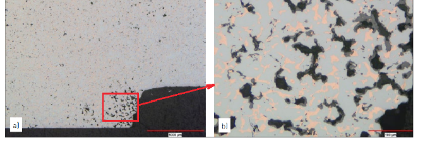
 P2-Fig.4 Cu-infiltrated part with an oxidation plus open porosity defect in the bottom corner of the section a).
Detail of the defect with copper and oxide in the pore structure can be seen in b) (un-etched)一個銅浸滲過的同時有氧化物夾雜的開放孔缺陷在照片a) 右下方,可以在b) 圖放大後清楚觀察到銅/ 氧化物與孔洞的分佈( 金相尚未進行蝕刻,銅的顏色是橘紅色,灰色是氧化物。黑色則是孔洞)
2.3 Metallographic examination 金相觀察
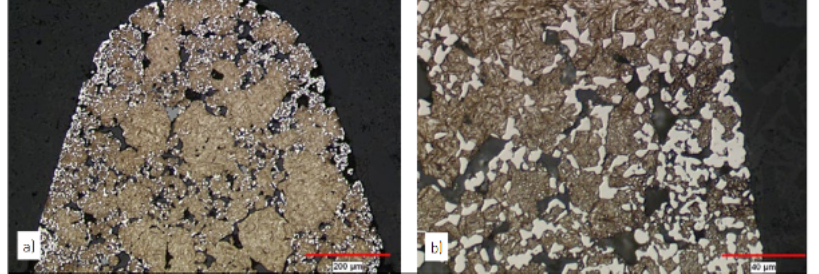
Metallographic examination, in both the aspolished and etched conditions, should begin at a low magnification and progress to higher magnifications only after sufficient information has been gathered and documented. The low magnifications provide a better overall view of the microstructure, where larger features and characteristics are more apparent. As the magnification is increased, more localized detail can be seen. Both the un-etched and etched analyses are needed to provide a complete picture of the microstructure. This is illustrated in P2-Fig.4 and 5 with both low and higher magnification images in each figure. P2-Fig.4 shows an example in the un-etched condition with a Cu-infiltrated sample containing excessive porosity and oxidation along the bottom corner. The low magnification image, P2-Fig.4a, shows the overall cross-section with the defect located in the lower corner of the image. Details of the porosity and oxidation in the porosity are seen in P2-Fig.4b. In addition to highlighting the benefits of using multiple magnifications, P2- Fig.4 illustrates how features may be distinguished by their characteristic colors and shades of grey before the sample is etched. In these images, the infiltrated Cu in the pore structure is the characteristic orange color. The dark grey oxides are located in the pore structure, but the oxides are lighter in color compared with the open porosity. In P2-Fig.5, gear teeth are observed after heavy carburization resulting from an atmosphere problem during secondary hardening. P2-Fig.5a shows carburization penetrating the tooth via the interconnected pore network and precipitating as the white carbides along the pore edges. P2-Fig.5b highlights the heavy carbide concentration along a tooth edge and shows the Martensite plus retained austenite microstructure in greater detail.不管是對拋光面還是蝕刻面的觀察,都應遵循先低倍再高倍的順序。先在較低倍率下獲得充足的資訊並予以記錄後,再切換到更高倍率下進行觀察。低倍率下具有較大的視場,可以對材料的顯微組織有一個整體了解。高倍率下則可以看到局部區域更清晰的細節。P2- 圖.4 和圖.5 所示為通常的金相照片模式( 低倍和高倍)。 P2- 圖.4 所示的例子為一個浸銅樣品的未蝕刻圖像,右下角區域有較多的孔隙和氧化物夾雜。從P2- 圖.4a 所示的低倍照片中我們可以看到截面上整體的組織特徵,並且可以發現缺陷位於圖像的右下角區域;P2- 圖P2-4b 顯示了缺陷區域的高倍圖像,即使沒有蝕刻,也可以從組成相的顏色和灰度差異中分辨出不同的組織結構,圖中橘紅色的部分為浸潤入孔隙中的銅,孔隙內壁的深灰色部分為氧化物,黑色部分為開孔隙。 P2- 圖.5 所示為在加硬處理中由於氣氛不當造成嚴重滲碳的齒輪零件的顯微組織。從P2-圖.5a 中可以看到,以連通孔隙為通道,滲碳反應穿透了整個齒形截面,白亮的碳化物沉積在孔隙邊緣。P2- 圖.5b 放大顯示了齒的外輪廓上富集的碳化物,同時還可以清晰地看到馬氏體與殘餘奧氏體等組織特徵。
 P2-Fig.5 Carburized gear teeth showing the locations of the high carbon content as the white precipitated carbides. In a), the tooth surface and pore edges are shown to be more heavily carburized than the interiors of the powder particles. Detail of the carbide concentration at the surface and the Martensite plus retained austenite icrostructure in the matrix is shown in b) (2 vol.% Nital + 4 wt.% Picral)照片a) 滲碳後的齒輪上的齒可以看到高含碳量的白色碳化物, 同時碳化物在表面比內部多,這是由於滲碳使表面形成較多的碳化物而成為馬氏體,b) 內部則可以清楚看到沒有轉變成馬氏體的殘留奧氏體,主要是碳含量不足( 使用蝕刻劑2vol.% Nital + 4 wt.% Picral)
2.3.1 Illumination of the specimen 光源
During the examination of both the as-polished and etched/stained surfaces, the light used to illuminate the specimen should be capable of reflecting all information from the prepared surface. When the features of interest have a characteristic colour, the particular colour must be contained in the light used by the microscope in order to be reflected back to the viewer. Historically, when most imaging and documentation was monochrome (black and white), the microscope light was filtered to enhance contrast between features due to the fact that all information was recorded as shades of grey. More recently, digital colour imaging is used in the majority of laboratories and the colour information contained on the sample surface is usable by the analyst. Consequently, the light used for viewing and documentation is usually white and contains the full visible spectrum.對拋光或蝕刻樣品進行觀察時,要選擇適當的光源對樣品表面進行照明,以保證所有的組織資訊都能得到反映。如果某一要觀察的組織有自己的特徵顏色,那麼光源中就應該包含有同一頻譜的光線,以保證觀察者能看到由該組織特徵反射回來的圖像。長期以來,大多數金相照片是黑白照片,不同組織的辨識是以圖像的灰度差別來加以區分,所以通常會在光源上加有色濾鏡來增加圖片的對比度。隨著技術的進步,數位化圖像技術已經被大多數實驗室採用,樣品表面的原始色彩資訊就需要被保留下來,因此,現在所用的光源通常就是包含了所有可見光譜的白光了。
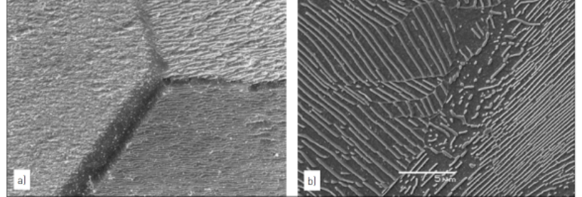
P2-Fig.6 Effect of an etchant on Ferritic and Pearlitic microstructures. In (a), the etchant has dissolved the surface of three grains at different rates, which were controlled by the orientation of the grains. The Pearlite in (b) is revealed by dissolution of the ferrite (dark gray background), while not affecting the carbides (series of white and light gray lines). Both (a) and (b) are secondary electron images (a) aqueous ammonium per-sulphate, (b) 4wt.% Picral在鐵素體和珠光體組織的腐蝕作用。 (a) 蝕刻劑溶解三晶粒的表面速度不同,這是由晶粒的方向取向所決定的。 (b) 中的珠光體是由鐵素體( 深灰色背景) 的溶解,碳化物( 白色和淺灰色線系列) 卻不受影響。 (a) 和(b)是二次電子圖像,蝕刻劑為:(a) 硫酸銨水溶液、(b) 4wt% 苦味酸
2.3.2 Chemical etching 化學蝕刻
Chemical etching is an electrochemical process where the microcells in the microstructure control the local activity of the etchant with the prepared surface. These cells contain small anodic and catholic regions that are affected to var ying degrees by the etchants. The cells are caused, not only by differences in composition (both chemical and microstructural), but by irregularities in crystal structure, grain boundaries, cold work or deformed regions, passivity layers, etc. In looking at the metallic portion of the microstructure, the relative positions of the phases and crystalline regions in the EMF series or the potential of the microcell determine the activity of the prepared surface with the etchant. This chemical activity creates microstructural contrast and causes the microstructure to be exposed. Examples of this are in seen in P2-Fig.6 as a Ferrite material, P2-Fig.6a, where the variation in crystal orientation determines the rate of solution by the individual grains and with Pearlite, P2-Fig.6b, where the ferrite is dissolved by the etchant and the carbides remain unaffected.化學蝕刻是一個電化學過程,樣品中各個微區的微電池效應決定了其與蝕刻劑之間的作用結果。在蝕刻劑的作用下,這些微電池中包含有強弱不同的微小陰極和陽極區域。影響這些微電池化學活性的因素不僅有成分上的差異( 化學成分差異或顯微組織差異),還有晶體缺陷、晶界、冷加工或冷變形區、鈍化層等。這些微電池在化學活性上的差異最終表現為顯微組織對比度上的差異,從而使得材料的顯微結構被顯露出來。 P2- 圖.6 是一種鐵基材料蝕刻後的顯微圖像。不同晶粒之間以及珠光體內兩棲相之間晶格取向上的差異影響到蝕刻過程中的溶解速度,顯露出來的圖像就如P2- 圖.6(a) 所示。從P2- 圖.6(b) 的高倍率圖像中可以看到,鐵素體相被蝕刻劑溶解,碳化物相則不受影響。■


